Arcane mixing techniques
From Gender and Tech Resources
Contents
Digital techniques basics
For conceptual basics from the atomic level up see Semiconductors, Diodes and Transistors https://www.youtube.com/watch?v=wPHG0DCWcC0 AND An Introduction to Logic Gates https://www.youtube.com/watch?t=10&v=95kv5BF2Z9E.
Gates
AND
The AND gate behaves in the same way as the logical and operator: Output is true when both inputs are true and any otherwise false:
| Input 1 | Input 2 | Output |
|---|---|---|
| 0 | 0 | 0 |
| 0 | 1 | 0 |
| 1 | 0 | 0 |
| 1 | 1 | 1 |
OR
The OR gate behaves like a logical inclusive or: Output is true if either or both of the inputs are true and false if both inputs are false:
| Input 1 | Input 2 | Output |
|---|---|---|
| 0 | 0 | 0 |
| 0 | 1 | 1 |
| 1 | 0 | 1 |
| 1 | 1 | 1 |
XOR
The XOR (exclusive-OR) gate acts as a logical either/or: the output is true if the inputs are different, and false if the inputs are the same:
| Input 1 | Input 2 | Output |
|---|---|---|
| 0 | 0 | 0 |
| 0 | 1 | 1 |
| 1 | 0 | 1 |
| 1 | 1 | 0 |
NOT
A logical inverter, alias NOT gate, has only one input and reverses logic state:
| Input 1 | Output |
|---|---|
| 0 | 1 |
| 1 | 0 |
NAND
A NAND gate works like an AND gate followed by a NOT gate:
| Input 1 | Input 2 | Output |
|---|---|---|
| 0 | 0 | 1 |
| 0 | 1 | 1 |
| 1 | 0 | 1 |
| 1 | 1 | 0 |
NOR
The NOR gate is a combination OR gate followed by an inverter:
| Input 1 | Input 2 | Output |
|---|---|---|
| 0 | 0 | 1 |
| 0 | 1 | 0 |
| 1 | 0 | 0 |
| 1 | 1 | 0 |
XNOR
XNOR (exclusive-NOR) gate is a combination of an XOR gate followed by an inverter:
| Input 1 | Input 2 | Output |
|---|---|---|
| 0 | 0 | 1 |
| 0 | 1 | 0 |
| 1 | 0 | 0 |
| 1 | 1 | 1 |
Universal gates
The NAND and the NOR gate can be considered to be "universal" because you can make any of the basic operations out of its combinations: an inverter, an OR gate or an AND gate. Non-inverting gates do not have this versatility since they can not make an invert.
Boolean algebra applied
Examples on the board
Serpent
Resources
Breadboards
You can buy solderless breadboards in a shop or online. Mind that you pick scalable like the SD-12 so you can hook up breadboards together and they become reuseful for other projects such as prototyping our own greenhouse sprinkler management systems.
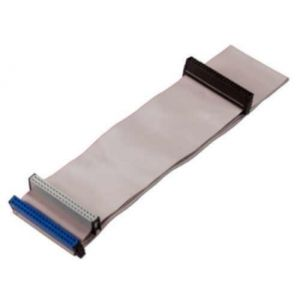
Alternatively (and the path I will take), start gathering and collecting IDC ribbon connectors (Floppy drive cables, old HD cables, SCSI cables) to build your own breadboards with. To do this, you will also need a solder iron, hot glue, wire (for example telephone wire will do), a small screw driver, and a clamp. This board will also be scalable. Fine grained scalable. :D
Chips
TTL Logic
TTL (transistor-transistor-logic) chips were developed with use of transistor switches for logical operations and defines the binary values as:
- 0 V to 0.8 V = logic 0
- 2 V to 5 V = logic 1
They are inexpensive, but draw a lot of power and must be supplied with +5 volts. Individual gates may draw 3 to 4 mA. The low power Schottky versions of TTL chips draw only 20% of the power, but are more expensive. These chips have LS in the middle of their model number.
- SN74LS00 (NAND) http://www.ti.com/product/sn74ls00
CMOS Logic
CMOS (complementary metal oxide semiconductor) chips are lower in power requirements (drawing about 1 mA) and operate with a wide range of supply voltages (typically 3 to 18 volts). The CMOS model number will have a C in the middle of it. A bigh drawback is extreme sensitivity to static electricity - they must be carefully protected from static discharges.
NMOS and PMOS Logic
PMOS and NMOS (p- and n-channel metal oxide semiconductors) offer the advantage of higher component density than TTL chips. They too are sensitive to damage from electrical discharge.


